¶ General
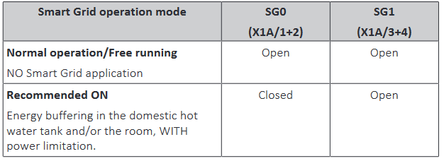
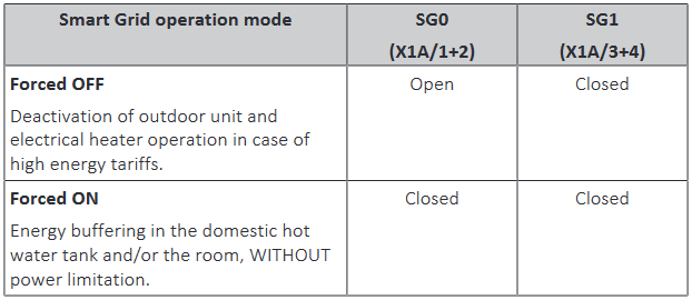
The Smart Grid Ready (SGR) interface is a (voluntarily) standardised interface to control heat pumps. It consists of two digital inputs (potential-free contacts) allowing you to put the heat pump into a total of 4 operating modes.


This manual is mainly written and verified for Daikin Altherma heatpumps, but can be used with other brands as well.
¶ Materials required
- SGR cookie with relay unit
- BRP069A61 LAN adapter
- Inline fuse holder, e.g. Farnell ref 3650464
- Suitable cartridge fuse, 230V max 6A, e.g. Farnell ref 1354593
- Mains Power Cord with wire ends, e.g. Farnell ref 1124386
- Some 0,75-1.5mm² flexible electrical wires
- A JST-XH 5p wire-ended connector, e.g. Tinytronics ref 002020
- Several meters of 4- or 8-wire twister pair cable
- (Optional) 4-pins solderless pluggable terminal blocks, e.g. these from AliExpress
¶ Assembly instructions
¶ Step 1: open up the heat pump
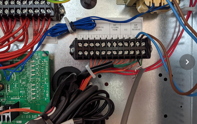
Check the manual of your heat pump where to locate the SGR input contacts.
Example for a Daikin Altherma 3
¶ Step 2: connect the cookie to the SGR contacts
- Disconnect power from the heat pump
- Open up the heat pump to gain access to the main circuit board.
- For Daikin: locate the X10A connector on the mainboard. This is a 5-pin shrouded connector placed semi-central on the heat pump circuit board.
- For other heat pumps: find a 5V power supply to provide power to the SGR cookie
If you have a Daikin, you can use the X10A connector:
| X10A | ESP32 |
|---|---|
| 1-5V | 5V |
| 2-TX | RX_PIN (goes to TX on the dongle) |
| 3-RX | TX_PIN (goes to RX on the dongle) |
| 4-NC | Not connected |
| 5-GND | GND |
Depending on the version number of your Altherma 3, the X10A might be upside down. Locate pin #1 by looking for the encircled 1 printed on the circuit board.
- Plug in the PTH cable, respecting the polarity of the connector. Be careful not to bend any pins!
Note that the X10A cable is not PTH-compliant. Your 5-pins PTH cable must have flat sides everywhere. If it has polarity 'ridges', it will not fit. Trim these down with small pliers and/or a file).
- Run a cable with at least 4 wires from the inside of the heat pump to the location you want to place the BRP adapter. Do not forget to make this cable enter the BRP adapter enclosure through a cable gland!
- Use the pluggable terminal blocks (or some other reliable form of connection) to connect the wire ends of the PTH cable to the cable running to the SGR cookie in the adapter. You only need to connect the 4 signal wires, you can cut off or wire wrap the
NCwire (so it doesn't touch anything on the circuit board).
- Connect the cable coming from the X10 connector the screw terminal of the SGR cookie according to the schematic below. Note: the wire colours in the schematic are for illustration only!
¶ Step 3: finalising
- Make sure all new or modified connections are safe and secure
- Close up the heat pump again
- Reapply power to the heat pump. The SGR cookie should receive power from the X10 connector of the external power supply and start up (LED going from red to green). The BRP adapter receives power through the P1/P2 interface, its LEDs should start blinking.
¶ Step 4: testing
Log-in to the Home Assistant. The SGR cookie should be present under MQTT devices. There you can put the device into the different modes manually as a test.
